EN

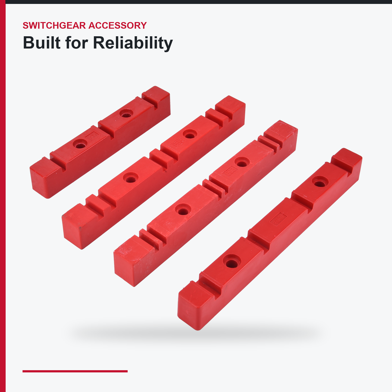
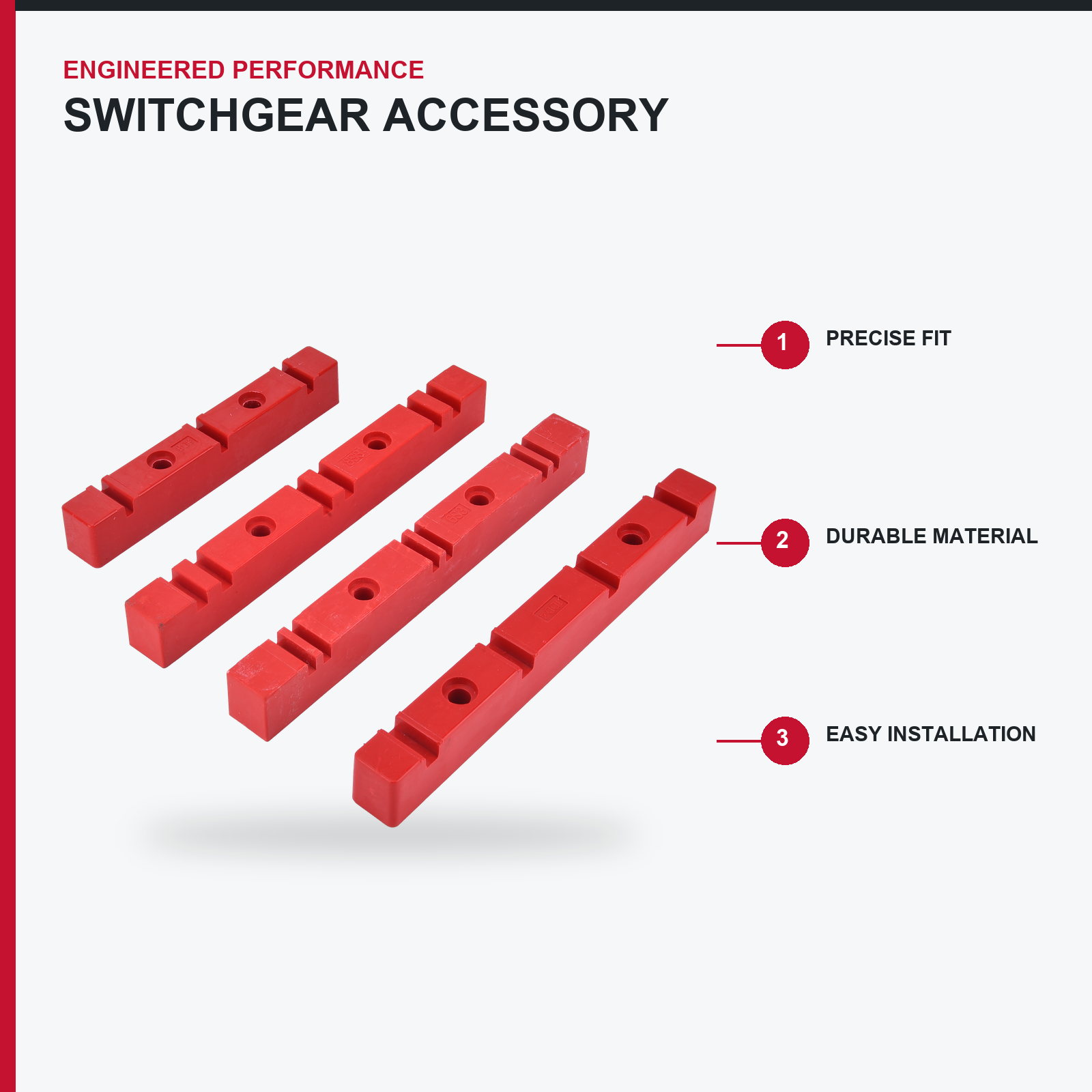
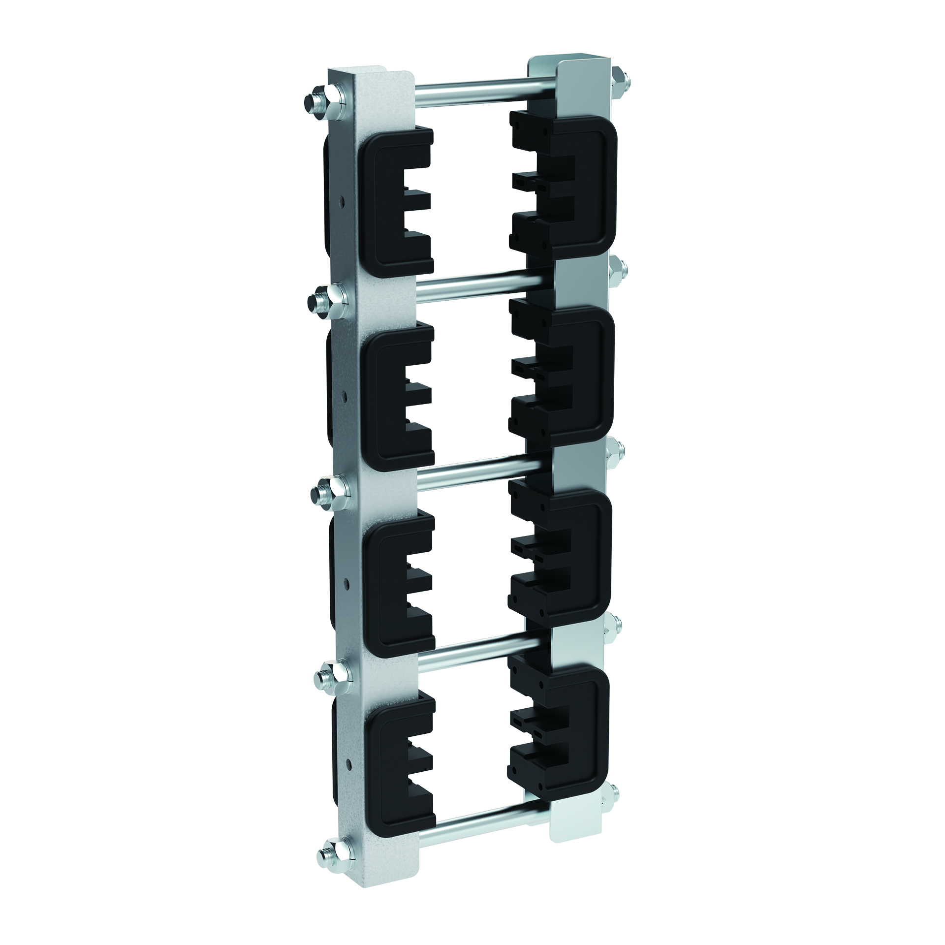
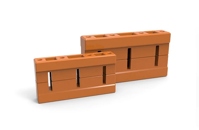
Busbar Holder - Clamping and Spacing the Busbar System, Rated to 73.5 kA Peak
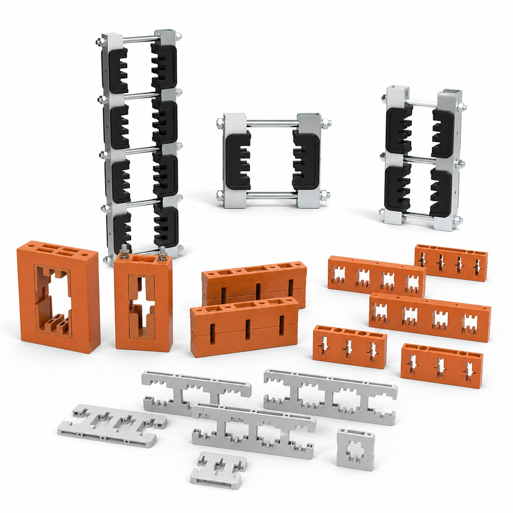
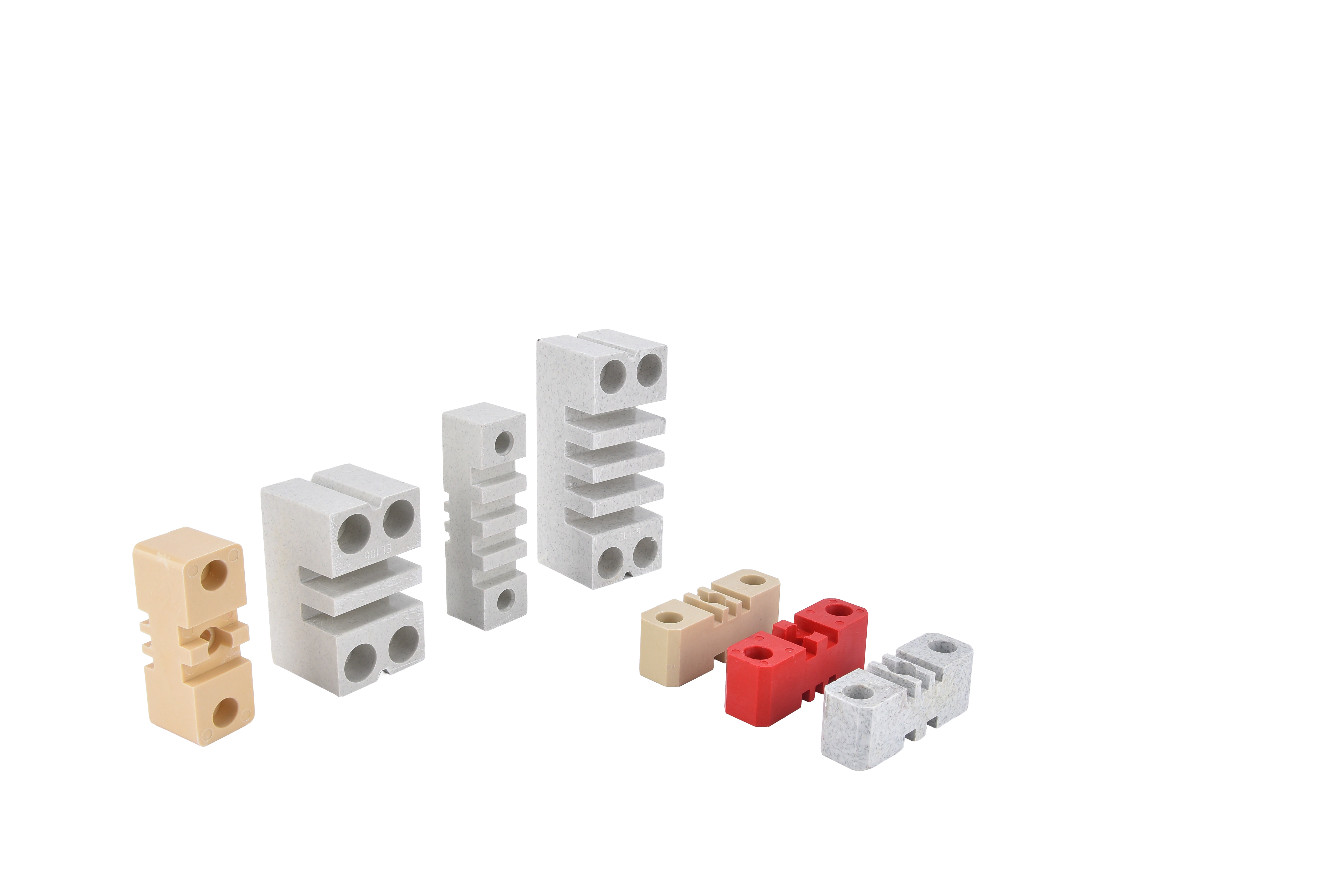
Busbar holders and clamps for LV switchgear. Flame-retardant moulded, 1-4 bars per phase, rated to 73.5kA peak with ZM clamps. Spacing tables.
- Overview
- Applications
- Technical Data
- Services
- Quality Control
- Recommended Products
Busbar Holder - Clamping and Spacing Busbar System, Rated to 73.5 kA Peak
Busbar holder clamps the bars, sets the phase spacing, and transfers short-circuit force into the frame. Together with the standoff insulator it is the busbar support system, and the fault rating of the whole chamber is a property of that system - not of the bars alone, and not of any single component.
WHAT ACTUALLY HAPPENS DURING A FAULT
Parallel conductors carrying a fault current repel and attract each other with force proportional to the square of the current. At 50 kA peak, the force on a busbar span is enough to bend copper and shear a fixing. The holder has to clamp firmly enough that the bar cannot move, distribute that force into the insulator without cracking it, and maintain phase spacing so the bars cannot touch. It has to do that once, correctly, possibly after fifteen years in service.
THE ZM CLAMP SYSTEM
On the M-Blokset platform the busbars are supported by ZM clamps moulded in flame-retardant PPO, rated for 73.5 kA peak withstand. PPO is chosen because it combines dimensional stability at elevated temperature with flame retardancy and good tracking resistance - a busbar chamber runs hot by design, and a clamp material that creeps under sustained temperature loosens the joint over time.
THE MISTAKE WE SEE MOST OFTEN
Mixing components. A holder from one supplier, an insulator from another, and a spacing figure copied from an old drawing. Each part looks fine and the assembly has no defensible fault rating at all. When an inspector asks for the short-circuit withstand evidence for the busbar chamber, there is nothing to show. Specify the holder and insulator as a matched system and you get a stated rating plus a spacing table you can put in the submittal.
WHAT WE SUPPLY
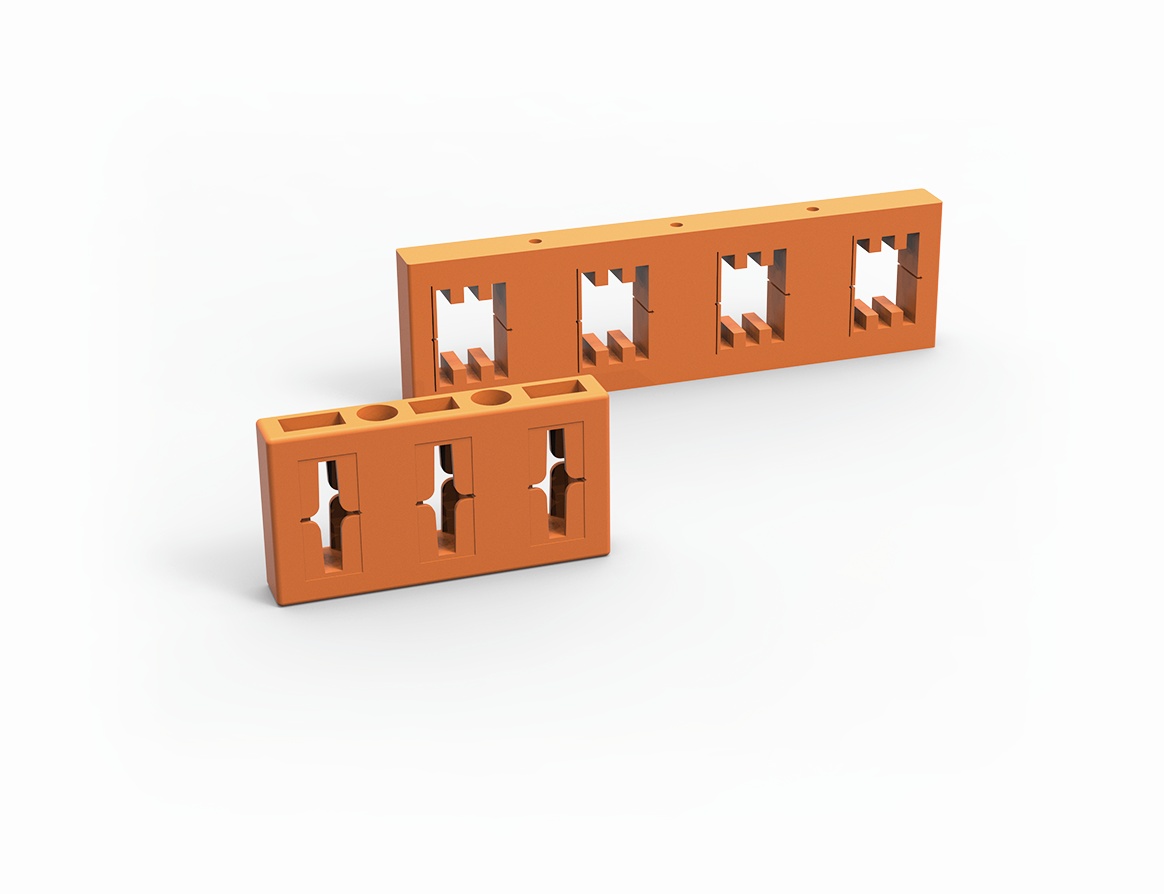
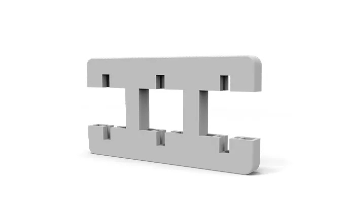
Holders for single, double, triple and quadruple bars per phase, across the standard bar widths and thicknesses, in three-phase and four-pole arrangements. Supplied with the bar compatibility table, the maximum support spacing against prospective peak fault current, and the clamping torque figure - so your workshop tightens to a number instead of to feel.
PRIMARY APPLICATIONS
- Main horizontal busbar clamping in GGD, GCK, GCS and MNS switchgear.
- Vertical distribution busbar support in withdrawable boards, where the drawer contacts mate.
- M-Blokset platform busbar support using the ZM clamp system.
- Busbar chamber support in XL-21 power distribution cabinets.
- Transformer LV connection busbar and neutral bar support.
- Busbar riser and trunking support in building distribution.
- Capacitor bank and generator connection panel busbars.
- Replacement holders for refurbishment of existing boards.
WHY MULTI-BAR ARRANGEMENTS NEED PARTICULAR CARE
Above about 2000A a phase is usually made of two, three or four parallel bars. The holder then also has to maintain the gap between parallel bars, because that gap is part of the current-sharing and cooling design. Bars clamped tight against each other run hotter and share current unevenly - a common defect in locally built high-current boards, and one that shows up on a thermographic survey years later.
REGIONAL FIT
- Middle East: switchroom ambient of 50-55 C against the IEC +40 C reference means the busbar chamber runs hot continuously. Clamp material creep resistance at sustained temperature is the property that keeps the joint tight over the design life.
- Africa: high-current installations at mining and cement plants, with vibration in addition to thermal cycling. Clamping torque discipline at build time is what keeps the joint sound.
- Russia and CIS: thermal cycling between heated and unheated periods; material must retain clamping force through the cycle.
- Eastern Europe: CE marked assemblies to EN 61439, where short-circuit withstand of busbar system forms part of the design verification file.
NOT SUITABLE FOR
Medium voltage busbar systems. Use as a cable support - use the Cable Clamp instead.
TECHNICAL DATA - Busbar Holder
Compliance: IEC 61439-1, IEC 60664-1, GB 7251.1
| Category | Item | Parameter Details |
| ELECTRICAL RATINGS | Rated voltage | up to 1000 V AC |
| Rated impulse withstand voltage (Uimp) | 8 kV / 12 kV depending on configuration | |
| Power-frequency withstand | 10 kV / 1 min minimum | |
| Comparative tracking index (CTI) | 600 minimum | |
| SYSTEM FAULT RATING | Rating basis | Rated as a system with the matched standoff insulators |
| Peak withstand current (main busbar) | up to 220 kA on main busbar arrangements | |
| M-Blokset ZM clamp peak withstand | 73.5 kA peak withstand | |
| Rated short-time withstand | matched to the assembly, up to 80 kA for 1 s | |
| Maximum support spacing | table supplied against bar section, phase spacing and prospective peak fault current | |
| MATERIAL | Main body | flame-retardant moulded thermoplastic or thermoset |
| M-Blokset ZM clamp | flame-retardant PPO, chosen for dimensional stability at sustained elevated temperature | |
| Flammability | UL 94 V-0 equivalent grade, batch documented | |
| Temperature index | continuous operation to +130 C on standard grade | |
| Water absorption | low | |
| BAR CAPACITY | Bars per phase | 1 / 2 / 3 / 4 |
| Bar width range | 12 / 15 / 20 / 25 / 30 / 40 / 50 / 60 / 80 / 100 / 120 mm | |
| Bar thickness range | 3 / 4 / 5 / 6 / 8 / 10 mm | |
| Parallel bar gap | maintained by the holder as part of the current-sharing and cooling design | |
| Pole arrangement | 3-phase, 3-phase and neutral, or 4-pole arrangements | |
| MECHANICAL | Clamping torque | stated per holder type and must be applied with a torque wrench |
| Fixing method | bolted to standoff insulators or directly to the frame | |
| Load rating | cantilever and clamping load rating stated per type | |
| Vibration suitability | suitable for industrial and mining installations | |
| ENVIRONMENT | Operating temperature | -40 C to +130 C |
| Relative humidity | up to 95% | |
| Pollution degree | 3 | |
| Altitude | up to 2000 m |
TESTING
Power-frequency withstand and insulation resistance on batch samples
Clamping force retention after thermal cycling on batch samples
Short-circuit withstand verification as a system with the matched insulators
Dimensional first-article inspection on every tool and production run
Visual inspection on every part
OPTIONS
Custom bar sizes and spacings to drawing | high-CTI grade for polluted
environments | high-temperature grade | tooling development under NDA
OEM branding and private-label packaging
THE PARTS YOU CANNOT RELIABLY BUY LOCALLY
Ask any panel builder in our markets what actually holds up a production batch and it is rarely the breaker. It is the busbar support that arrived cracked, the clamp that does not fit the bar size on the drawing, the handle that has no matching lock, the hinge that does not carry a loaded door. We manufacture over 2,000 of these components ourselves, with 38+ patents behind them, precisely because the open market does not supply them consistently.
1. FULL-RANGE SUPPLY FROM ONE SOURCE
Insulators, busbar holders, cable clamps, hinges, locks, handles, operating mechanisms, isolating contacts, mounting rails and cabinet hardware - one supplier, one packing list, one container. You stop chasing eight vendors for one cabinet.
2. DIMENSIONAL DATA AND FIT-UP DRAWINGS
Every part ships with a dimensioned drawing, bar or panel compatibility table, torque figure and material specification. Your designer can lay out the busbar chamber without ordering samples first.
3. MATCHED SYSTEMS, NOT LOOSE ITEMS
Insulators, holders and clamps are designed as a system with a stated peak withstand rating. Mixing brands is how a busbar chamber that looked fine on paper fails a short-circuit test. Specify the set and the fault rating is a design value, not a hope.
4. CUSTOM AND OEM PARTS
Non-standard sizes, alternative thread forms, brand-marked parts and private-label packaging. Tooling development for volume customers, with drawings held under NDA.
5. STOCK, MOQ AND CONSOLIDATION
Low minimum order quantities on standard items so a distributor can hold a working stock rather than a warehouse. Consolidated loading with cabinets, drawers and devices in one shipment.
6. MATERIAL AND COMPLIANCE DOCUMENTATION
Material certificates, flammability and tracking-index data for insulating parts, plating thickness reports for conductive parts, RoHS declarations, and the component evidence your IEC 61439 verification file needs.
7. AFTER-SALES
24-hour technical response. Free replacement for any part that fails on dimensional or material grounds. Parts kept to the same drawing revision so a repair in year five still fits.
8. COMMERCIAL TERMS
FOB, CFR, CIF, DDP, Ex-Works. Trade Assurance, T/T, L/C. Samples supplied for fit-up verification before volume.
QUALITY CONTROL - THE SMALL PARTS THAT DECIDE WHETHER A BOARD PASSES
Component-level defects are cheap to prevent and expensive to discover. A cracked insulator, an under-plated contact or a clamp that is 2 mm out of tolerance does not show up in the workshop; it shows up during the dielectric test, or during a short circuit. Incoming and in-process inspection is therefore applied to every batch.
MATERIAL CONTROL
1. Raw material verified against certificate on receipt - polymer grade, copper purity, steel grade and thickness.
2. Insulating materials qualified for flammability rating, comparative tracking index and dielectric strength; flame-retardant grades confirmed by batch documentation.
3. Metal parts checked for grade, thickness and surface condition before forming.
DIMENSIONAL CONTROL
4. First-article inspection on every tool and every production run, with a full dimensional report against the drawing.
5. In-process sampling to the agreed AQL, with critical dimensions measured on calibrated gauges.
6. Thread quality and insert pull-out force checked on threaded and insert-moulded parts.
7. Fit-up verification against the mating part - a holder is checked with the actual bar section, not only against a number on a drawing.
PERFORMANCE TESTING
8. Insulating parts: power-frequency withstand voltage, insulation resistance, mechanical bending and cantilever load, and thermal cycling on batch samples.
9. Conductive parts: plating thickness by coating gauge, adhesion, contact resistance, and temperature rise at rated current.
10. Mechanical parts: operating force, endurance cycling, and load test on hinges, locks and clamps.
11. Corrosion: salt spray testing on plated and coated parts, with hours to first defect recorded.
12. Environment: humidity and heat ageing on samples, relevant to Gulf and tropical African installations.
APPEARANCE AND PACKING
13. Visual inspection for cracks, voids, flash, burrs, plating defects and colour consistency.
14. Marking legibility and correctness.
15. Quantity, packing integrity and part-number labelling verified before the carton is sealed.
DOCUMENTATION AND SYSTEM
Material certificates, dimensional reports, test records and RoHS declarations supplied on request and formatted for inclusion in your IEC 61439 verification file. ISO 9001 quality management with recorded, root-caused and closed non-conformances. Samples supplied for your own fit-up verification before volume; third-party inspection by SGS, BV, TUV or Intertek accepted.