EN

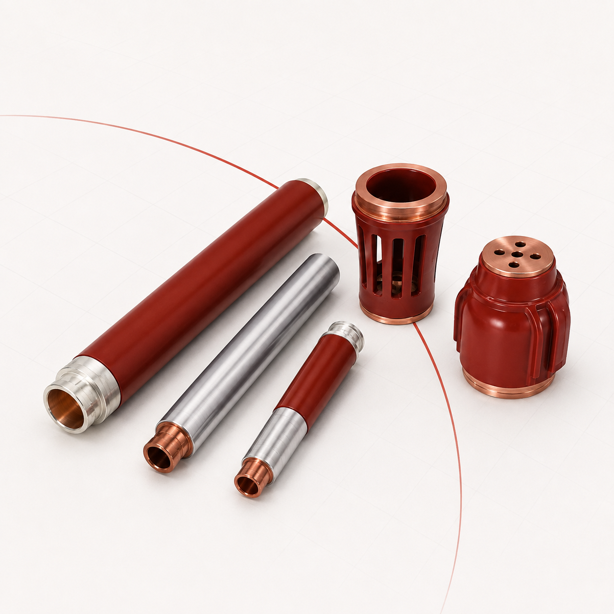
Insulated Contact Arm 1250A – 3150A
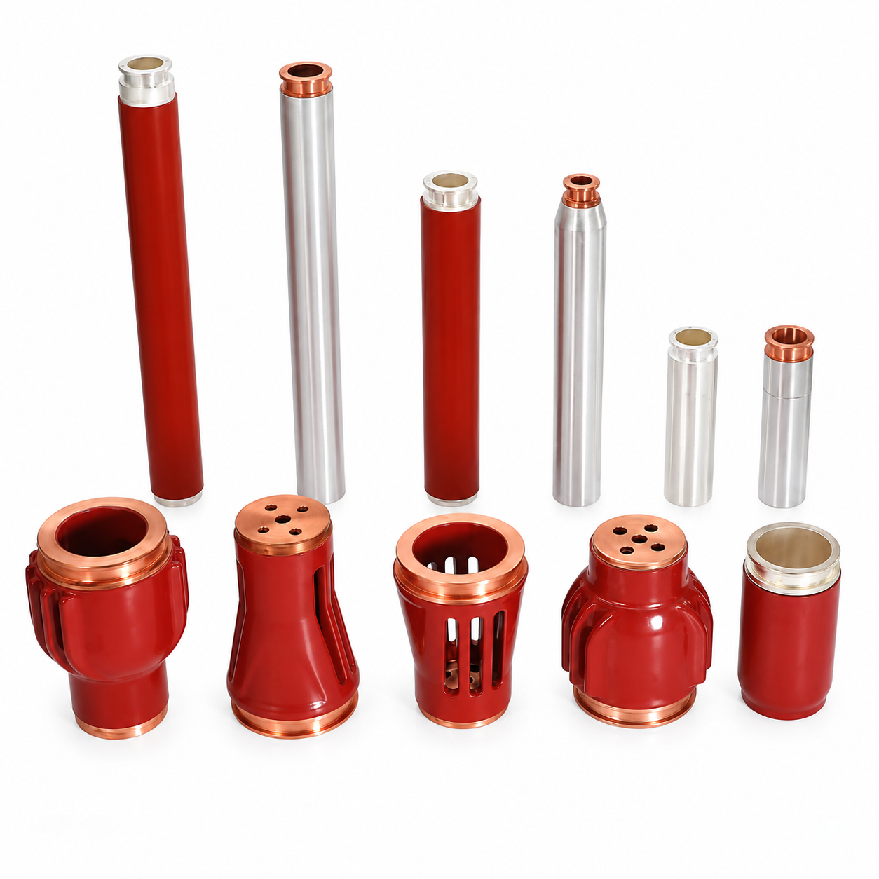
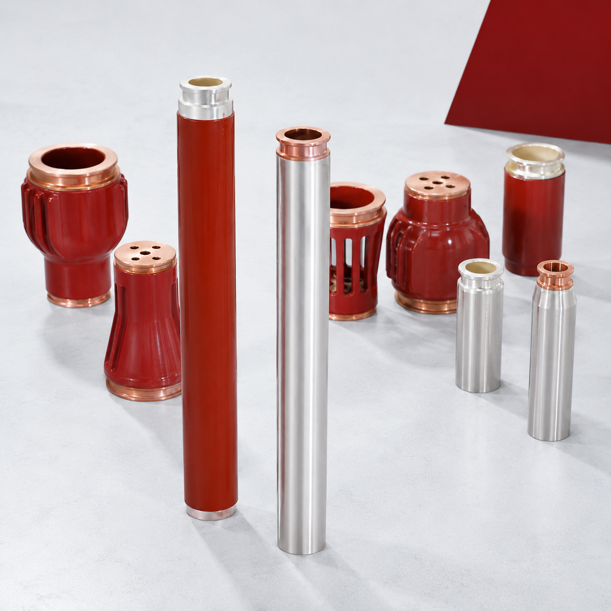
T2 copper contact arm with vulcanized silicone insulation jacket. Prevents phase-to-phase flashover in humid Gulf environments. Our Insulated Contact Arms are critical components designed for the lower arm bus connections of withdrawable vacuum circuit breaker (VCB) handcarts. Rated from 1250A up to 3150A, these arms incorporate a vulcanized silicone rubber or heat-shrink insulation jacket over the primary conductor. This design provides a robust dielectric barrier, significantly reducing the risk of phase-to-phase flashover in compact switchgear. Engineered for durability in challenging environments, these arms are essential for maintaining the insulation integrity and long-term reliability of medium-voltage power distribution systems, particularly within humid and polluted industrial settings.
- Overview
- Applications
- Technical Data
- Services
- Quality Control
- Recommended Products
Insulated Contact Arms - 1250A to 3150A for Vacuum Circuit Breakers
The contact arm is the copper conductor that connects a vacuum interrupter terminal to the breaker trolley's tulip contact, carrying full rated current through the moving assembly. Upper and lower arms are fitted per pole. MOLDVOLT manufactures insulated contact arms rated 1250A to 3150A for 12kV and 24kV withdrawable circuit breakers.
WHY THE INSULATION JACKET EXISTS
On a bare-copper contact arm, the phase-to-phase clearance inside the breaker is fixed by the pole centre distance - 210mm at 12kV, 230mm at 24kV. In clean, dry air that is adequate. In the conditions our markets actually operate in, it often is not.
Humidity and condensation reduce air's dielectric strength. Conductive dust bridges part of the gap. Salt fog deposits a hygroscopic film that becomes conductive when damp. Under any of these conditions the effective clearance falls below the design value, and a phase-to-phase flashover across the contact arms becomes possible - a fault that occurs inside the breaker itself, destroys the unit and usually the panel compartment with it.
A vulcanised silicone rubber or heat-shrink insulation jacket over the arm removes the air path as the sole insulating barrier. The jacket is why the same breaker design can serve a humid coastal African substation, a Gulf site with airborne salt and sand, and a CIS panel subject to condensation during winter start-up.
CONDUCTOR AND CURRENT DENSITY
T2 grade electrolytic copper verified by mill certificate, with cross-section sized to carry rated current within the 70K temperature rise limit of IEC 62271-1. This matters more on a contact arm than on a static busbar because the arm is enclosed within the breaker assembly where convective cooling is limited - an arm sized as though it were free-air busbar will run hot.
Contact faces at both ends are silver plated to 8-12 microns, verified by X-ray fluorescence per batch, with tin plating available for coastal and industrial atmospheres.
MECHANICAL DUTY
The arm carries the mechanical load of the vacuum interrupter contact force on every operation - tens of thousands of cycles over the breaker's life - while remaining dimensionally stable so that contact alignment is maintained. Bends and terminations are formed rather than welded where possible, avoiding the grain-structure changes and stress concentrations that welded joints introduce.
SUPPLY
Supplied as OEM production to drawing and as replacement spares for VS1, VD4 and equivalent breakers. Where the original part is obsolete, send a sample or dimensioned drawing and we will produce an equivalent.
PRIMARY APPLICATIONS
- Upper and lower contact arms in VS1-12, VS1-24, VSG-12 and VSG-24 vacuum circuit breakers.
- Contact arms in VD4, VPR and equivalent withdrawable breakers.
- Connection conductors between vacuum interrupter terminals and trolley tulip contacts.
- Fixed breaker conductor arms in panel-mounted VCB installations.
- Replacement spares for breaker refurbishment across the installed base in Africa, CIS and the Middle East.
- Breaker refurbishment and switchgear service workshop stock.
- Panel builder and breaker assembler production stock.
- Retrofit projects where a breaker is rebuilt to serve an existing panel.
WHY THIS IS A REFURBISHMENT STAPLE
Vacuum circuit breakers are frequently rebuilt rather than replaced: the vacuum interrupters and mechanism may be serviceable while the contact arms have suffered plating loss, overheating discolouration, insulation jacket degradation or mechanical damage from a through-fault. Replacing the arms restores the breaker at a small fraction of replacement cost.
This is a significant activity across our markets, where an aged installed base of VS1 and VD4 breakers remains in service long after the original manufacturer has withdrawn support. Limited spare parts availability is consistently cited as a leading barrier in Middle East and African electrical procurement, and contact arms are among the items most often needed and least often stocked.
WHEN TO REPLACE
Replace when any of the following is found: insulation jacket cracking, hardening or tracking marks; plating loss or pitting on contact faces; discolouration indicating past overheating; deformation from through-fault electromagnetic forces; or contact resistance measurably above the commissioning baseline.
SELECTION GUIDANCE
Specify by rated current, breaker model and pole centre distance, arm geometry and terminal hole pattern, insulation type - vulcanised silicone or heat-shrink - and plating appropriate to the environment.
REGIONAL FIT
- Middle East: airborne salt and sand plus high ambient temperature make the insulation jacket essential rather than optional; tin plating for coastal sites.
- Africa: humid coastal and industrial environments with very high refurbishment demand.
- Russia and CIS: condensation during winter start-up is a real flashover risk; verified low-temperature jacket flexibility is required, since some insulation materials embrittle at -40 C.
- Eastern Europe: standard IEC service in temperate switchrooms.
NOT SUITABLE FOR
Current ratings above the selected type. Breaker models where geometry has not been confirmed. Applications requiring a bare, uninsulated conductor.
| Category | Parameter | Value / Specification |
|---|---|---|
| ELECTRICAL | Rated voltage | 12 kV / 24 kV breaker service |
| Rated current | 1250 / 1600 / 2000 / 2500 / 3150 A | |
| Short-time withstand current | 25 kA / 31.5 kA for 4 s, matched to breaker rating | |
| Peak withstand current | 63 kA / 80 kA | |
| Rated temperature rise | Within 70 K per IEC 62271-1 at rated current | |
| Contact resistance | Measured and recorded per piece | |
| CONDUCTOR | Base material | T2 grade electrolytic copper |
| Material verification | Mill certificate retained per batch | |
| Conductivity | Minimum 97% IACS | |
| Cross-section | Sized to rated current with allowance for restricted convective cooling inside a breaker enclosure | |
| Forming | Bends and terminations formed rather than welded where geometry permits, avoiding grain-structure change and stress concentration | |
| Contact face plating | Silver plated 8 – 12 microns standard; tin plating available for coastal and industrial atmospheres | |
| Plating verification | X-ray fluorescence measurement, recorded per batch | |
| INSULATION JACKET |
Type | Vulcanised silicone rubber, or heat-shrink polyolefin |
| Dielectric strength | 20 kV/mm minimum | |
| Comparative tracking index (CTI) | 600 minimum for silicone | |
| Temperature range | −40 °C to +150 °C for silicone; −40 °C to +105 °C for heat-shrink | |
| Flame retardancy | UL94 V-0 grade available | |
| Adhesion | Fully bonded to conductor, no air gap at the interface | |
| Coverage | Full arm length excluding contact faces and terminal areas | |
| MECHANICAL | Arm geometry | To drawing, matched to breaker model and pole centre distance |
| Pole centre distance compatibility | 210 mm (12 kV) / 230 mm (24 kV) | |
| Terminal hole pattern | To customer specification | |
| Mechanical life | Matched to breaker rated mechanical endurance, 30,000 operations minimum | |
| Compatibility | VS1, VD4, VPR and equivalent breaker footprints | |
| SERVICE CONDITIONS |
Operating temperature | −40 °C to +105 °C |
| Humidity | Suitable for tropical and high-humidity service | |
| Pollution | Insulation jacket specified for humid, dusty, saline and condensing environments | |
| TESTING (Every Piece or Batch) |
Contact resistance measurement | — |
| Plating thickness verification | By X-ray fluorescence | |
| Insulation jacket dielectric withstand test | — | |
| Dimensional inspection | Critical fit dimensions 100% checked | |
| Material conductivity verification | — | |
| Visual inspection | For jacket defects, voids and plating damage | |
| Temperature rise verification | On type samples | |
| Low-temperature jacket flexibility | For GOST 15150 service | |
| OPTIONS | Insulation type | Vulcanised silicone or heat-shrink insulation |
| Coastal / industrial plating | Tin plating for coastal and industrial atmospheres | |
| Custom geometry | Custom geometry, length and terminal pattern to drawing | |
| Branding & packaging | Customer part numbering and packaging | |
| Flame-retardant jacket | UL94 V-0 jacket | |
| Low-temperature verified jacket | For GOST 15150 climatic service | |
| Reverse engineering | From physical sample for obsolete breakers |
SPECIFICATION AND SOURCING
- Send a drawing, a sample or a photograph with the existing part number and we will identify the equivalent and confirm fit before you commit to an order.
- Reverse engineering from a physical sample where the original part is obsolete or the OEM no longer supplies it - common for aged KYN28, HXGN and imported panels still in service across Africa, CIS and the Middle East.
- OEM and private-label production to your drawings, with your part numbering and packaging.
- Material and plating selected for the destination environment: silver plating for lowest contact resistance indoors, tin plating for coastal and industrial atmospheres where salt fog and sulphides attack silver.
WHY THIS MATTERS COMMERCIALLY
Limited local technical expertise and difficult spare parts supply are consistently identified as the main barriers in Middle East and African electrical markets. A panel is out of service for as long as it takes the part to arrive. We hold consumable items in stock and quote fleet spares lists against your installed base so the part is on the shelf before it is needed.
QUANTITY AND LEAD TIME
- Stock items dispatched from inventory; typical production lead time 15-25 days for standard specifications.
- Low minimum order quantities on standard parts - we supply single-piece emergency replacements as well as bulk production volumes.
- Air freight for breakdown situations, sea freight consolidation for planned restocking.
TESTING AND DOCUMENTATION
- Routine testing per applicable IEC standard with results supplied per batch.
- Material certificates, plating thickness reports and dimensional inspection records available on request.
- Certification support for SONCAP, KEBS PVoC, SABER and GOST R submissions where the component ships as a standalone consignment.
AFTER-SALES
- Technical response within 24 hours; application engineering support for fit, assembly torque and maintenance intervals.
- Warranty against manufacturing and material defects: 12 months from delivery.
- Framework and call-off agreements available for panel builders, utilities and switchgear service workshops.
MATERIAL CONTROL
- Copper verified as T2 grade electrolytic copper or specified copper-silver alloy, with mill certificates retained per batch.
- Epoxy resin verified as cycloaliphatic grade with documented gel time, viscosity and filler ratio; general-purpose bisphenol resin is not accepted for outdoor or high-humidity service because of its poorer tracking and UV resistance.
- Plating thickness measured by X-ray fluorescence and recorded per batch - typically 8-12 microns of silver on contact surfaces. Under-plating is invisible on delivery and only shows up years later as a thermal fault, so this is measured rather than assumed.
PROCESS CONTROL
- APG (Automatic Pressure Gelation) casting under controlled mould temperature, injection pressure and gel time, producing a void-free matrix. Voids initiate partial discharge, and partial discharge is what eventually punctures an insulator in service.
- Vacuum degassing of resin before injection to eliminate entrapped air.
- Controlled post-cure cycle to relieve internal stress and stabilise dimensions.
- Contact finger spring force calibrated and verified against specification, ensuring uniform current sharing across all fingers.
ROUTINE TESTING - EVERY PIECE OR EVERY BATCH
- Partial discharge test on insulation components, typically below 10 pC at 1.1 times rated voltage.
- Power-frequency withstand voltage test.
- Contact resistance measurement on current-carrying parts.
- Dimensional inspection against drawing, with critical fit dimensions 100% checked.
- Visual inspection for cracks, voids, plating defects and surface finish.
- Mechanical load testing on insulators against rated cantilever strength.
TYPE TESTING
- Insulators verified to IEC 60168 and IEC 62217; contacts and conductive parts verified for temperature rise within the 70K limit of IEC 62271-1 at rated current.
- Thermal cycling and, for parts destined for coastal service, salt-spray corrosion testing.
TRACEABILITY AND SYSTEM
- ISO 9001 quality management system.
- Batch numbering linking finished parts back to raw material certificate and process records.
- Certificates of conformity, material certificates and test reports issued with each shipment.
- Retained samples held per production batch for future reference in the event of a field query.