EN

JN15A-12 Indoor Earthing Switch
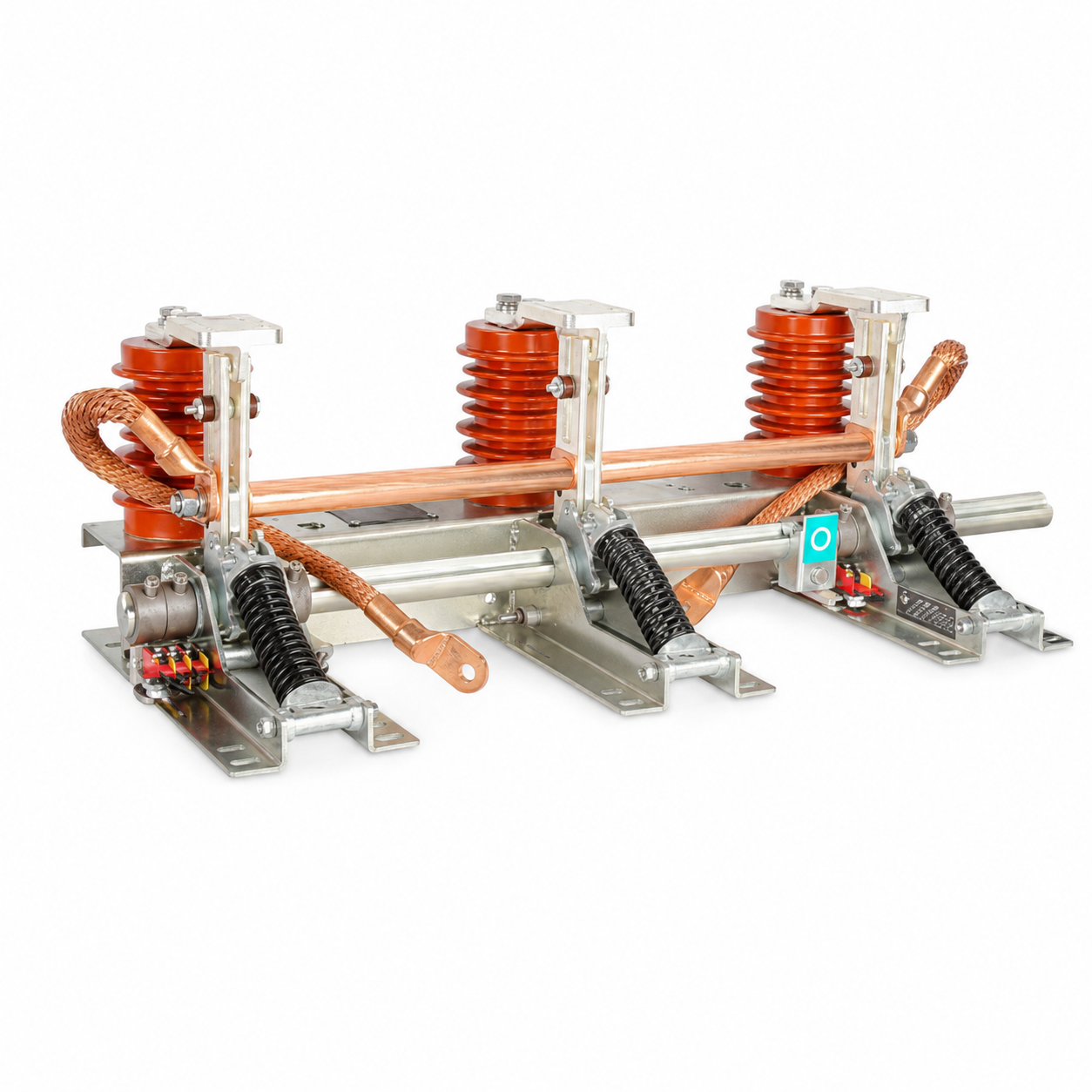
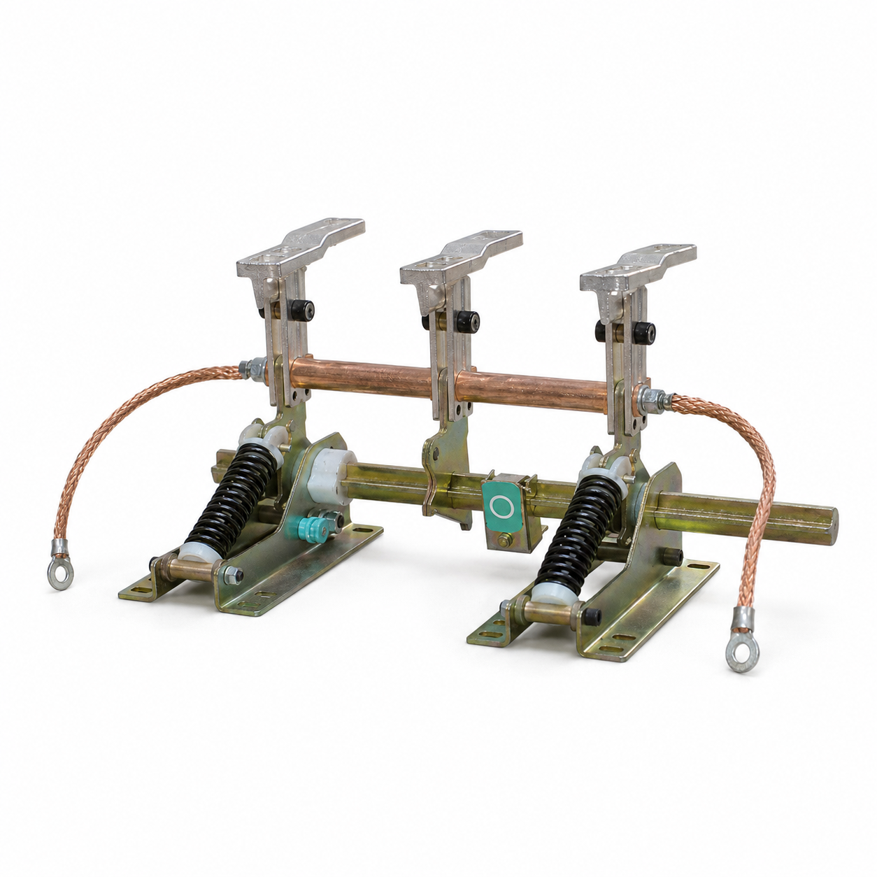
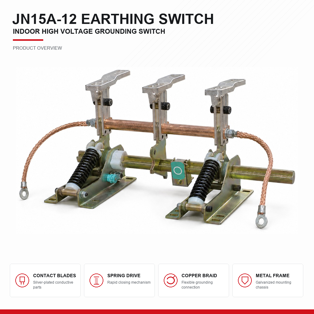
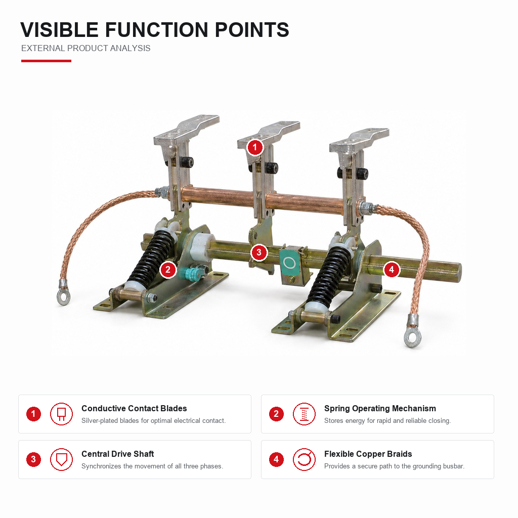
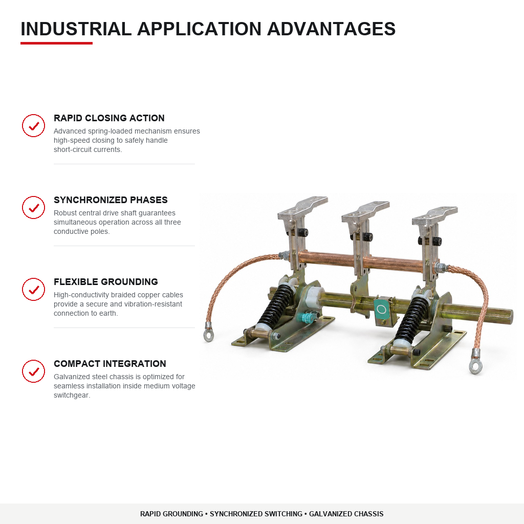
JN15A-12 indoor earthing switch is a three-phase grounding device rated at 12kV, designed for installation in the cable compartment of KYN28-12 switchgear. Built to IEC 62271-102, this earthing switch features a spring-loaded rapid closing mechanism for high-speed operation, a central drive shaft for synchronized three-phase action, and silver-plated contact blades for reliable electrical connection. Rated for 50kA peak making current and 20kA short-time withstand for 4 seconds, this indoor earthing switch provides visible earth connection for de-energized conductors before maintenance. The galvanized steel chassis supports seamless integration into medium voltage switchgear assemblies.
- Overview
- Applications
- Technical Data
- Services
- Quality Control
- Recommended Products
JN15A-12 Indoor Earthing Switch - 12kV, Three-Pole
JN15A-12 is a three-pole indoor earthing switch for 12kV switchgear, installed in the cable compartment of KYN28 metal-clad panels and equivalent assemblies. It connects de-energised cables and busbars to earth before maintenance work begins, providing the visible, positively-interlocked earth that safe working procedures depend on. Built to IEC 62271-102.
MAKING CAPACITY IS THE SPECIFICATION THAT MATTERS
An earthing switch spends its entire service life doing nothing, and is then closed by an operator who believes the circuit is dead. Sometimes it is not. The single most important rating is therefore short-circuit making capacity - the ability to close onto a live circuit and hold that fault current until upstream protection clears it, without the contacts welding shut or the arc escaping the compartment.
JN15A-12 is rated 50kA peak making current and 20kA short-time withstand for 4 seconds. A switch that cannot make onto a fault is not a safety device, it is a liability, and this is the rating to check first when comparing suppliers.
THREE-POLE SIMULTANEOUS OPERATION
All three phases are driven from a single shaft and earth simultaneously. This removes the possibility of leaving one phase un-earthed - an error that is invisible from outside the panel and potentially fatal to anyone working downstream.
INTERLOCKING
The earthing switch is mechanically interlocked with the circuit breaker and the cable compartment door, enforcing the correct sequence in hardware rather than by procedure: the breaker must be open and withdrawn before the earthing switch can close; the earthing switch must be closed before the cable compartment door can open; and the breaker cannot be racked in while the earth is applied. Interlocking is what converts a safe procedure into a safe system.
CONSTRUCTION
Copper alloy contact blades with silver-plated contact surfaces, mounted on cycloaliphatic epoxy support insulators. Manual lever operation with a direct-driven mechanical position indicator, so the operator sees actual blade position rather than a mechanism proxy. Optional auxiliary switch blocks provide earth-applied status to protection relays and SCADA.
MARKET FIT
The 12kV class serves 11kV networks across the Middle East and Africa and 10kV networks in Russia, CIS and Eastern Europe. ASTA type-test certification is available where utility and EPC procurement requires third-party witnessed evidence rather than a manufacturer's own report - a common requirement in Gulf and African tender documents.
PRIMARY APPLICATIONS
- Cable compartment earthing in KYN28-12 metal-clad switchgear - the standard and highest-volume application.
- Busbar earthing in bus-section and bus-riser panels before maintenance.
- Feeder earthing in fixed-type switchgear and ring main cabinets.
- Transformer circuit earthing before primary-side work.
- Earthing points in compact and packaged substations.
- Retrofit into aged switchgear where the original earthing switch is worn, damaged or no longer supported.
- Industrial plant MV switchboards requiring lockable earthing for permit-to-work systems.
- Utility distribution substations on 10kV and 11kV networks.
WHY EVERY FEEDER NEEDS ONE
Applying portable earths instead of a fixed earthing switch introduces two risks that fixed switches eliminate: the earth may be applied to the wrong circuit, and it must be applied by someone reaching into a compartment that has not yet been proven dead. A fixed, interlocked earthing switch removes both. This is why utility specifications across all four target regions mandate integral earthing switches on cable feeders.
REGIONAL FIT
- Middle East: 11kV switchgear, with ASTA certification frequently required by SEC, DEWA, KAHRAMAA and EPC contractor procurement.
- Africa: 11kV networks - robust interlocking is especially important where operating staff turnover is high and formal permit systems may be inconsistently applied.
- Russia and CIS: 10kV networks, GOST R certification, GOST 15150 climatic versions with low-temperature grease.
- Eastern Europe: 10kV networks to EN 62271-102.
NOT SUITABLE FOR
Outdoor installation without an enclosure. Systems above 12kV - specify JN17 for 24kV. Applications requiring high-speed fault-making earthing at 35kV and above - specify JN22. Motorised remote earthing - specify JN17, which offers a motorised variant.
TECHNICAL DATA - JN15A-12 Earthing Switch
| Parameter | Value |
| Compliance | IEC 62271-102, GB 1985 |
| ELECTRICAL RATINGS | |
| Rated voltage | 12 kV |
| Rated frequency | 50 Hz / 60 Hz |
| Rated power-frequency withstand voltage (1 min) | 42 kV to earth / 48 kV across isolating distance |
| Rated lightning impulse withstand voltage (BIL) | 75 kV peak / 85 kV across isolating distance |
| Rated short-circuit making current | 50 kA peak |
| Rated short-time withstand current | 20 kA for 4 s |
| Rated peak withstand current | 50 kA |
| Number of poles | 3, simultaneous operation from a single shaft |
| MECHANICAL | |
| Operation | Manual lever |
| Operating angle | 90 degrees, open to earthed |
| Position indication | Mechanical indicator, direct-driven from the main shaft |
| Mechanical life | 2,000 operations minimum |
| Making operations at rated making current | 2 operations minimum |
| Interlocking | Mechanical interlock with circuit breaker and cable compartment door |
| Padlocking | Provision for padlock in both open and earthed positions |
| CONSTRUCTION | |
| Contact blade material | Copper alloy, silver plated |
| Support insulators | Cycloaliphatic epoxy resin |
| Frame | Hot-dip galvanised or powder-coated steel |
| Earthing terminal | M12 bolt for main earth conductor |
| Mounting | Cable compartment of KYN28-12 and equivalent panels |
| Auxiliary switch | Optional, up to 4NO4NC |
| Weight | Approximately 20 - 30 kg |
| SERVICE CONDITIONS | |
| Ambient temperature | -25 C to +55 C |
| Altitude | Up to 1000 m standard; up to 2000 m on request |
| Relative humidity | Daily average not exceeding 95% |
| Installation | Indoor, within metal-enclosed switchgear |
| CERTIFICATION | |
| Type tested | IEC 62271-102 |
| ASTA type-test certificate | Available on request - note that an ASTA certificate is signed by an ASTA observer who takes responsibility for the report, which is why utility and EPC procurement treats it differently from a manufacturer's own test record |
Auxiliary switch block for position signalling to relays and SCADA | padlocking kit | extended operating shaft for front-of-panel operation | low-temperature grease for GOST 15150 climatic versions | ASTA type-test certification | custom shaft length and mounting to suit non-standard panels
PRE-SALES SELECTION
- Application review against your duty: rated current, breaking capacity, operating sequence, and expected switching frequency.
- Retrofit and replacement sizing. Send us the existing unit's model, pole-centre distance and mounting dimensions and we will confirm interchangeability before you order.
- Grid verification: 12kV class for 10kV (Russia/CIS) and 11kV (Middle East/Africa) networks; 24kV for 20kV and 22kV; 40.5kV for 35kV. Saudi Arabian supply verified at 60Hz.
- Coil, motor and auxiliary-contact configuration specified to your control voltage (AC/DC 110V or 220V) and SCADA interface requirement.
- Low-temperature variants with cold-rated grease and anti-condensation heating for CIS winter service.
MARKET ACCESS AND DOCUMENTATION
- Type-test reports to IEC 62271-100 / IEC 62271-102 / IEC 62271-103 as applicable, issued with the shipment.
- Third-party certification (KEMA, ASTA, CESI, TUV) available where tender documents require witnessed evidence rather than a manufacturer's report.
- Certification support for SASO SABER, SONCAP, KEBS PVoC, ICIGI and GOST R submissions, including HS-code classification (Nigeria has required 10-digit HS codes since March 2025).
TESTING AND DELIVERY
- 100% routine testing before dispatch: power-frequency withstand, contact resistance, mechanical characteristic curve, timing test, and auxiliary circuit verification.
- Individual test report supplied per serial number.
- Export packing with desiccant and moisture barrier; palletised for consolidated shipment.
- Documentation: routine test report, type-test certificate, dimensional drawing, wiring schematic, O&M manual, spare parts list.
AFTER-SALES
- Installation and commissioning guidance, remote support or engineer dispatch.
- Maintenance training covering mechanism inspection, contact wear measurement and vacuum interrupter integrity testing.
- Wear parts (coils, contacts, mechanism components) held in stock for rapid replacement.
- Technical response within 24 hours; multilingual manuals in English, Russian, French and Arabic.
- Warranty: 18 months from delivery or 12 months from commissioning, whichever expires first.
TYPE TESTING
- Type tested to the applicable IEC standard - IEC 62271-100 for circuit breakers, IEC 62271-102 for earthing switches and disconnectors, IEC 62271-103 for load break switches.
- Verified for rated short-circuit breaking and making capacity, short-time withstand current, power-frequency and lightning impulse withstand, temperature rise, and mechanical endurance across the full rated operating sequence.
- Third-party certification from KEMA, ASTA, CESI or TUV available where the tender requires witnessed evidence.
VACUUM INTERRUPTER CONTROL (where applicable)
- Every interrupter is vacuum-integrity tested before assembly; vacuum degradation is the dominant failure mode in a VCB and is not visible externally once installed.
- Contact stroke, over-travel and contact wear allowance measured and recorded per pole.
- Interrupters sourced only from qualified manufacturers with batch traceability.
IN-PROCESS INSPECTION
- Insulating components partial-discharge tested before assembly.
- Mechanism spring force and charging characteristic verified against specification.
- Pole-centre distance and mounting interface dimensions checked against drawing - critical for retrofit interchangeability.
- Plating thickness on current-carrying contacts verified per batch.
ROUTINE TESTING - 100%, NO SAMPLING
- Power-frequency withstand voltage across the open contacts and to earth.
- Main circuit contact resistance measurement.
- Mechanical characteristic curve: closing time, opening time, contact bounce, and three-phase simultaneity.
- Operating mechanism function at minimum, rated and maximum control voltage - a unit that only operates at nominal voltage will fail during a real disturbance when station battery voltage sags.
- Auxiliary switch continuity and position signalling verification.
- Serialised routine test report issued with every unit.
TRACEABILITY AND SYSTEM
- ISO 9001 quality management system.
- Serial number traceability to vacuum interrupter batch, mechanism batch and insulation component batch.
- Test records retained for the warranty period and available on request.
ENVIRONMENTAL QUALIFICATION
Where the destination environment exceeds IEC reference conditions we qualify against it: elevated-ambient temperature-rise verification for Gulf service, salt-spray testing for coastal sites, and low-temperature operation verification with cold-rated lubricant for GOST 15150 climatic versions.