Switchgear Protection Solutions: 7 Key Strategies for Industrial Reliability

All Categories
Customer Perspectives on Switchgear Protection Solutions

Customer Perspectives on Switchgear Protection Solutions

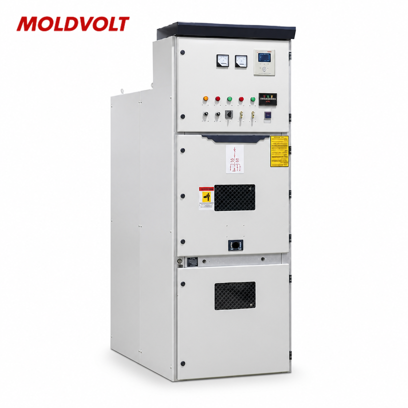
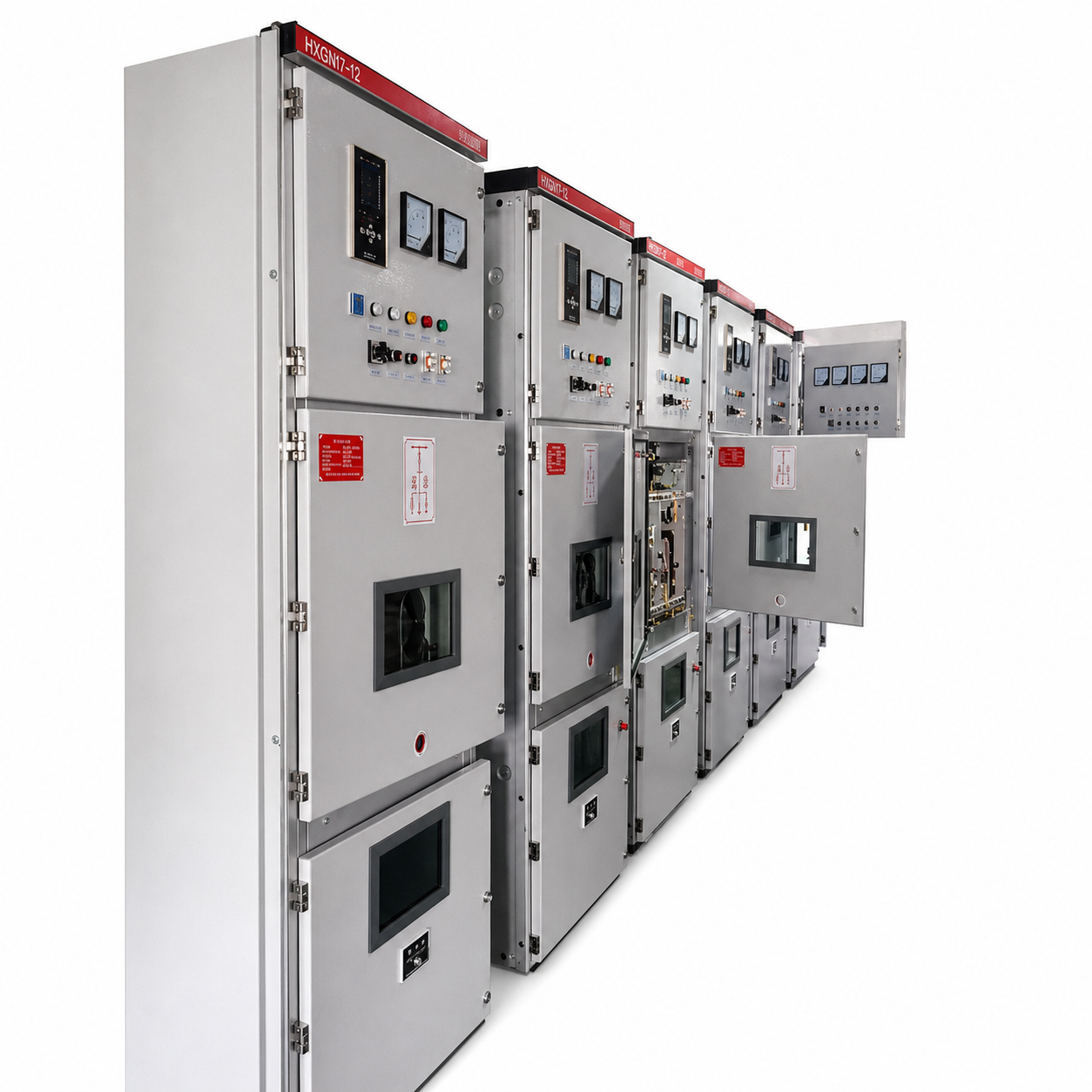
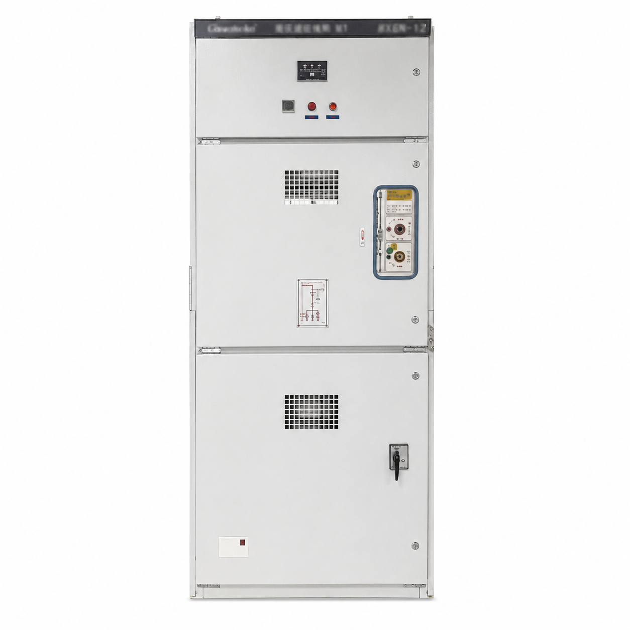
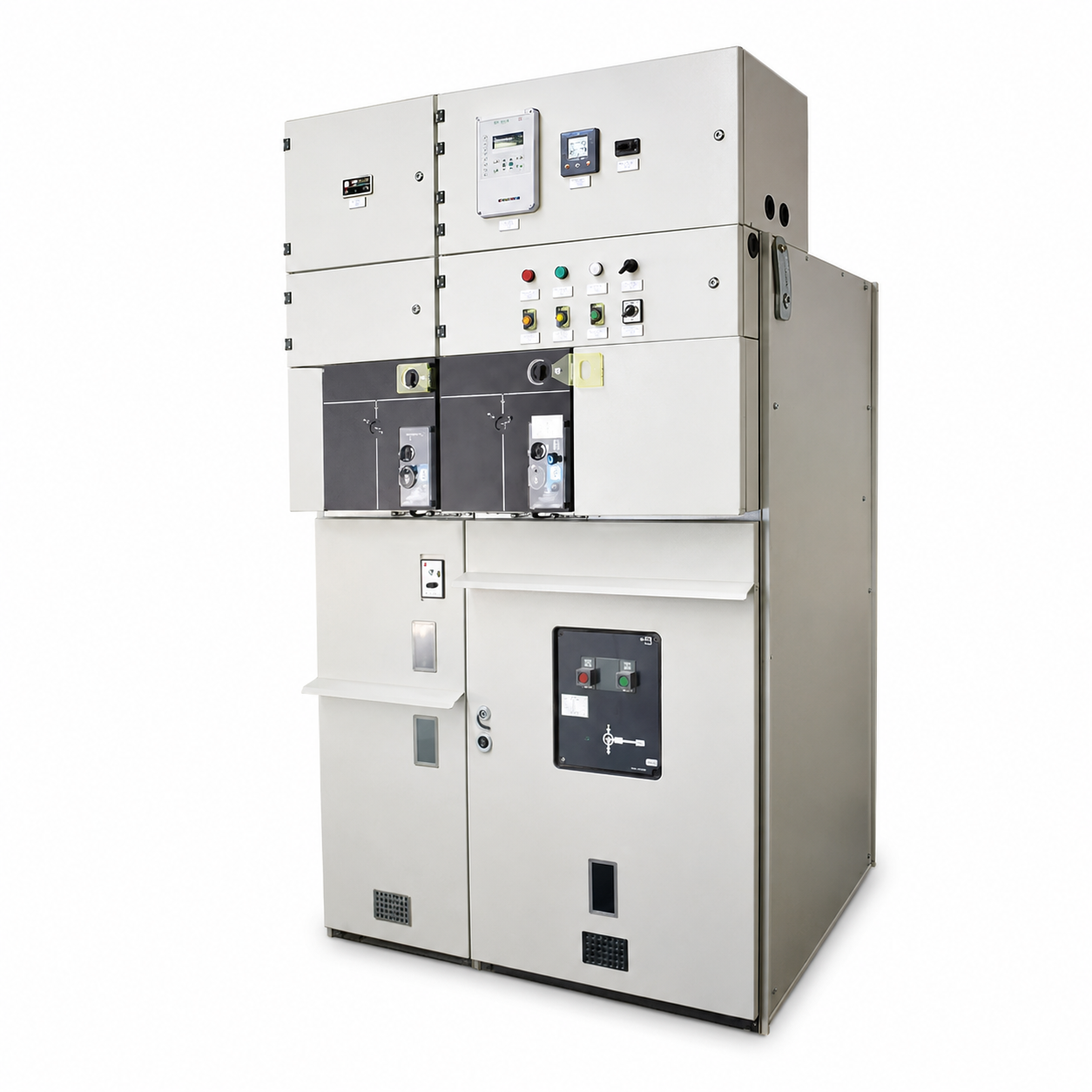
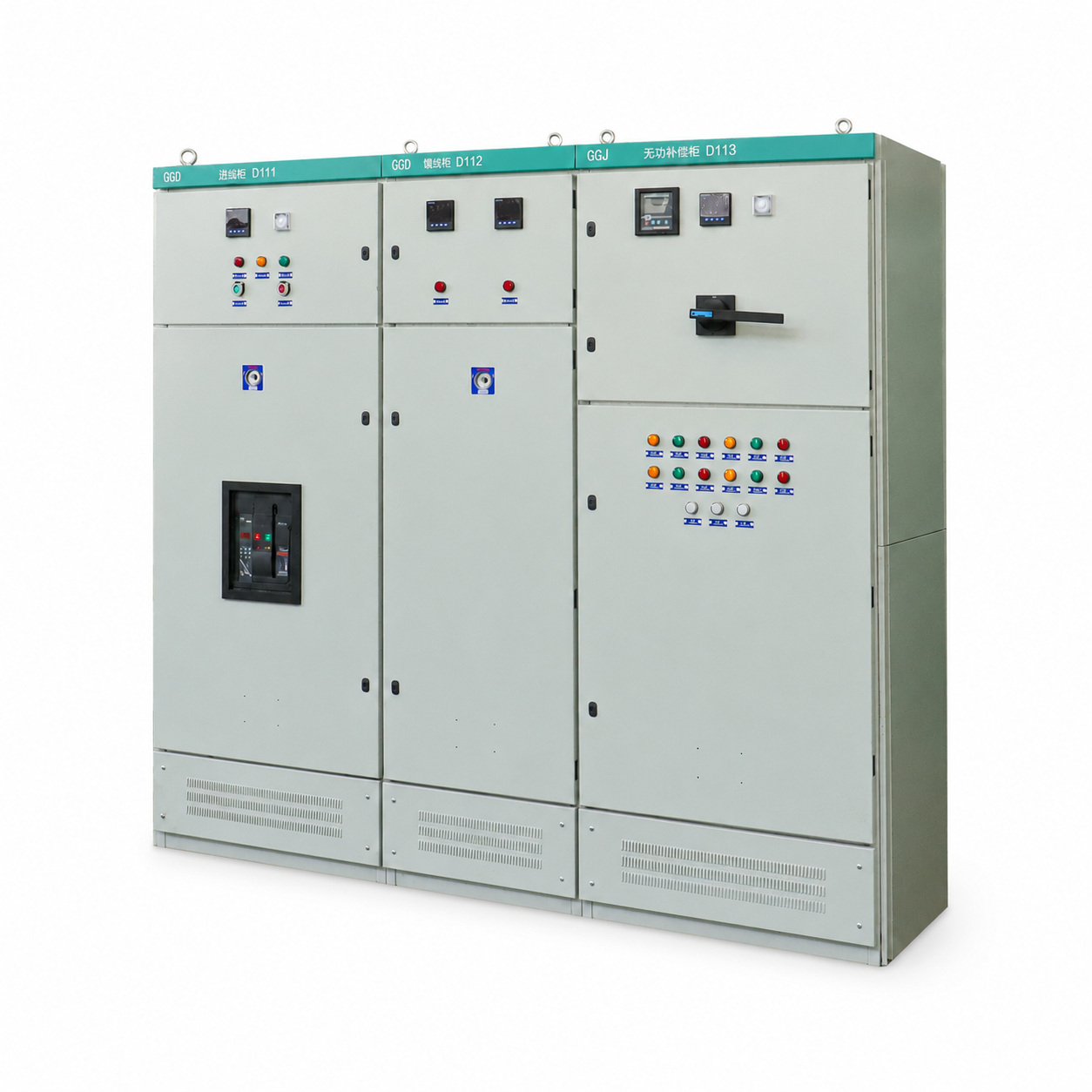
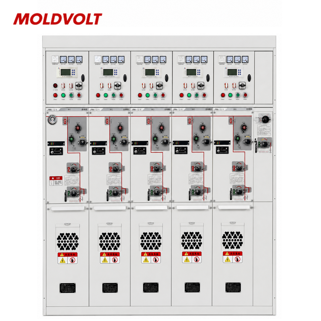
Protection of switchgear is essential for detecting abnormal electrical conditions and helping prevent damage to equipment, cables, and connected loads. Depending on the installation, protection systems may incorporate circuit breakers, overcurrent relays, earth-fault protection, differential protection, and arc-flash mitigation measures. Selection depends on voltage level, prospective fault current, load characteristics, and the required operating sequence. For example, a manufacturing plant may use coordinated overcurrent protection to isolate a faulty motor feeder without unnecessarily disconnecting unaffected circuits. Proper relay settings, suitable interrupting ratings, and regular functional testing help maintain protection performance. Engineering verification and compliance with applicable standards support safe operation across industrial, commercial, and utility electrical networks.
Get A Quote

Case Study

Switchgear Protection for Manufacturing Facilities

Manufacturing facilities depend on coordinated switchgear protection to manage faults affecting motors, production equipment, and auxiliary circuits. Protective relays monitor electrical parameters and initiate circuit breaker operation when configured fault conditions are detected. Engineers should assess motor starting currents, overload characteristics, prospective short-circuit levels, and upstream protection settings. For example, a production plant may use separate feeder protection to isolate a faulty motor circuit while maintaining power to unaffected equipment. Periodic relay testing and breaker maintenance help identify performance issues before they compromise protection functions. Final settings should be verified against the electrical design and the equipment manufacturer's recommendations.

Switchgear Protection for Commercial Buildings

Commercial buildings require protection against overloads, short circuits, and earth faults across distribution boards, HVAC systems, elevators, and essential services. Properly selected circuit breakers and protective relays help disconnect affected circuits when abnormal conditions occur. Protection coordination is important where multiple distribution levels supply different building areas. For example, a fault on a downstream lighting circuit should be evaluated against upstream breaker settings to reduce unnecessary interruption to other loads. Engineers should consider available fault current, conductor ratings, selectivity requirements, and applicable electrical codes. Routine inspection and testing help verify that protective devices remain suitable for the building's operating conditions.

Switchgear Protection for Utility Substations

Utility substations require protection schemes designed around transformers, busbars, incoming supplies, and outgoing feeders. Depending on the network configuration, protection may include overcurrent, earth-fault, transformer differential, busbar differential, and breaker-failure functions. Engineers must coordinate relay settings with fault calculations, equipment ratings, and upstream and downstream protection systems. For example, a feeder fault should trigger the intended circuit breaker while limiting unnecessary disconnection of other network sections. Commissioning tests, secondary injection testing, and documented maintenance procedures help verify protection functionality. The final scheme should follow the approved protection study, equipment specifications, and applicable utility requirements.

Related products

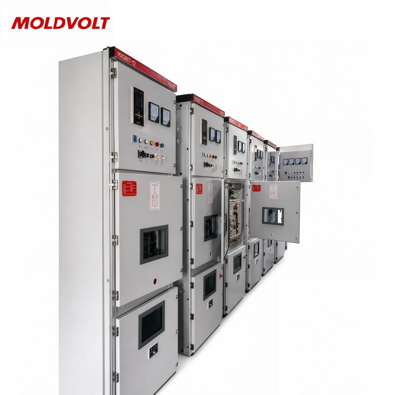
Switchgear protection combines protective devices, sensing equipment, control circuits, and switching mechanisms to detect abnormal electrical conditions and isolate affected circuits. Common applications include industrial plants, commercial buildings, substations, and infrastructure facilities. Depending on system requirements, protection functions may include overcurrent, earth-fault, differential, undervoltage, and breaker-failure protection. Effective protection begins with an accurate understanding of the electrical network. Engineers assess rated voltage, load current, prospective short-circuit levels, conductor capabilities, and the characteristics of connected equipment. Relay settings must be coordinated so that the intended protective device operates under the specified fault conditions. This selectivity helps reduce unnecessary interruptions to unaffected circuits. For example, a manufacturing facility may use feeder protection to isolate a motor fault while keeping other production areas energized, where the protection design permits. In substations, transformer and busbar protection may require dedicated schemes based on the system configuration and risk assessment. Protection performance also depends on suitable circuit breaker ratings, correct wiring, commissioning tests, and periodic maintenance. Buyers should request protection coordination studies, relay setting documentation, and relevant test records. Applying appropriate standards and following manufacturer instructions helps maintain dependable protection throughout the equipment's service life.
Frequently Asked Questions

What is switchgear protection?

Switchgear protection uses protective relays, circuit breakers, and associated sensing circuits to detect abnormal electrical conditions and isolate affected circuits. Depending on the system, it can respond to overloads, short circuits, earth faults, or other defined conditions. Correct configuration helps protect equipment and support electrical system reliability.
Common functions include overcurrent, earth-fault, differential, undervoltage, and breaker-failure protection. The appropriate combination depends on voltage level, equipment type, network configuration, and fault study results. Transformer and busbar installations may require specialized protection schemes, while ordinary feeders often use coordinated overcurrent and earth-fault functions.
Protection coordination helps ensure that the protective device closest to a fault operates as intended, where selectivity is achievable. This can limit unnecessary outages and help maintain service to unaffected circuits. Engineers establish settings by evaluating fault currents, device characteristics, conductor ratings, and the requirements of the overall electrical network.
Testing frequency depends on equipment type, operating environment, manufacturer recommendations, applicable standards, and the facility's maintenance program. Commissioning checks and periodic functional testing help verify relay operation, trip circuits, and breaker performance. Qualified personnel should establish inspection intervals based on risk assessment, operating history, and documented maintenance requirements.
Engineers typically need the single-line diagram, load data, equipment ratings, prospective fault currents, transformer characteristics, and upstream protection settings. Cable information and operating requirements are also important. These details support protection coordination studies, relay setting calculations, and selection of suitable circuit breakers and protective functions.

Related article

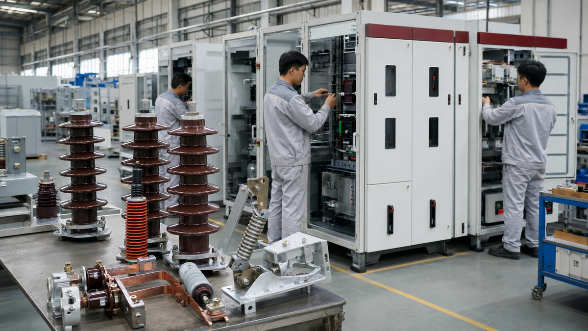
From High-Voltage Insulators to Low-Voltage Switchgear: A Vietnamese Manufacturer’s Transformation, Together with Us‌

08

Sep

From High-Voltage Insulators to Low-Voltage Switchgear: A Vietnamese Manufacturer’s Transformation, Together with Us‌

View More
Cabinet corrosion resistance determines service life in coastal engineering sites.

23

Sep

Cabinet corrosion resistance determines service life in coastal engineering sites.

Why Coastal Environments Accelerate Cabinet CorrosionThe chloride-humidity synergy: How salt aerosols and sustained high RH drive electrochemical degradationCoastal atmospheres subject cabinet enclosures to a uniquely aggressive combination of airbor...
View More
Insulator dimension design follows international high voltage standards strictly.

16

Oct

Insulator dimension design follows international high voltage standards strictly.

Core IEC Standards Governing Insulator Dimension Design IEC 60383: Mechanical and Electrical Requirements for Ceramic and Glass Insulators The IEC 60383 series defines the mechanical and electrical test regimes that ceramic and glass insulators mus...
View More
Cable clamp vs cable tie: which one delivers long term stability in panels?

27

Oct

Cable clamp vs cable tie: which one delivers long term stability in panels?

Mechanical Performance Under Thermal Stress Polymer creep and thermal expansion mismatch in nylon cable ties at 60–85°C Nylon 6/6 cable ties undergo measurable mechanical degradation when exposed continuously to 60–85 °C. At the...
View More

Customer Testimonials

Michael Turner

Effective switchgear protection coordinates circuit breakers, protective relays, and fault detection settings to help manage electrical faults. Correctly selected protection functions support equipment safety and operational continuity in industrial facilities.

David Wilson

Coordinated protection settings help distinguish faults and support selective circuit isolation. Reviewing fault levels, load characteristics, and relay settings helps engineers improve electrical system reliability and simplify maintenance planning.

Get a Free Quote

Our representative will contact you soon.
Email
Mobile/WhatsApp
Name
Company Name
Message
0/1000
Coordinated Protection Functions

Coordinated Protection Functions

Switchgear protection should be designed around the electrical network's fault levels, equipment ratings, and operating requirements. Overcurrent and earth-fault relays commonly protect distribution feeders, while transformer or busbar applications may require differential protection. Coordination studies help determine suitable pickup values, operating times, and relationships between upstream and downstream devices. For example, a factory with multiple motor feeders may require settings that accommodate normal starting currents while responding appropriately to fault conditions. Engineers should verify relay characteristics against conductor capabilities and circuit breaker performance. A documented protection study supports commissioning, future adjustments, and systematic maintenance of the electrical installation.
Testing, Monitoring, and Maintenance

Testing, Monitoring, and Maintenance

Protection equipment requires appropriate commissioning and ongoing verification to maintain dependable operation. Checks may include relay configuration, current transformer polarity, trip circuit continuity, breaker operation, and communication between protection devices. The exact testing scope depends on the equipment design and applicable maintenance procedures. In a utility substation, documented functional testing can help identify issues affecting feeder or transformer protection before they lead to operational problems. Maintenance teams should retain test records, review relay settings after system changes, and follow manufacturer instructions. Qualified personnel should perform testing using approved procedures and suitable equipment, with findings documented for future inspections and protection assessments.

Get a Free Quote

Our representative will contact you soon.
Email
Mobile/WhatsApp
Name
Company Name
Message
0/1000