
 EN
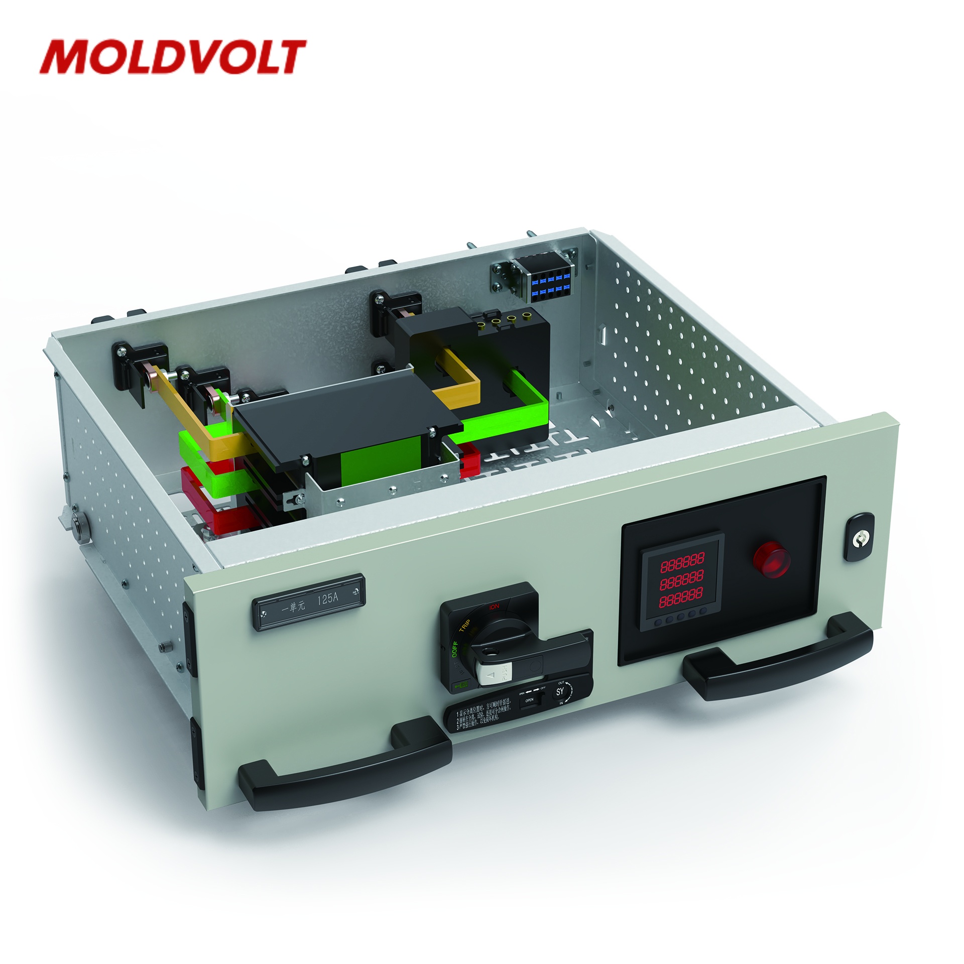
Insulation Integrity and Dielectric Strength Verification
Megger testing of busbars, cables, and instrument transformer circuits
Megger testing is a foundational pre-commissioning check for electrical switchgear, measuring insulation resistance (IR) across busbars, power cables, and instrument transformer circuits. A DC voltage—typically 500 V for low-voltage circuits (≤1 kV) and 1 kV or 5 kV for medium-voltage systems—is applied between conductors and from each phase to earth. Resistance is recorded after 60 seconds and compared against minimum acceptance criteria: for clean, dry insulation, the one-minute IR should exceed 1 MΩ per kV of rated voltage plus 1 MΩ (e.g., ≥11 MΩ for a 10 kV system). Values below this threshold—or a downward trend over time—often signal moisture ingress, surface contamination, or thermal degradation.
Cross-checking phase-to-phase and phase-to-ground readings helps localize weak spots before energization. In instrument transformer circuits, persistently low IR may indicate saturated insulating oil or degraded bushings, warranting oil sampling and further diagnostics. Documenting these baseline measurements establishes a critical reference for predictive maintenance and long-term insulation health monitoring.
AC/DC high-potential (hi-pot) testing aligned with IEC 62271-1 and IEEE C37.20.2
High-potential (hi-pot) testing verifies that switchgear can withstand transient overvoltages without dielectric breakdown—exposing latent manufacturing flaws or installation damage. Per IEEE C37.20.2 and IEC 62271-1, new metal-enclosed switchgear must endure a one-minute power-frequency withstand test at a voltage determined by its rated maximum voltage. For example, a 15 kV-class assembly typically undergoes a 34 kV rms AC test, while DC hi-pot—commonly used for cables and busway—is applied at up to 1.7 × the AC rms value. The test involves gradual voltage ramp-up, sustained application for the specified duration, and real-time leakage current monitoring; flashover or abrupt current rise indicates failure.
Modern digital hi-pot testers separate capacitive charging, absorption, and resistive leakage components, enabling precise interpretation. Acceptance requires no disruptive discharge and stable, low leakage current consistent with factory baselines. Crucially, test voltage must never exceed the manufacturer’s certified level—over-testing risks degrading otherwise sound insulation. Successful completion confirms the assembly’s ability to safely manage both normal operation and temporary overvoltages, underpinning long-term dielectric reliability.
Protection System Functional Validation for Electrical Switchgear
Trip circuit supervision, breaker timing, and relay pickup verification per ANSI/IEEE C37.101
Trip circuit supervision (TCS), per ANSI/IEEE C37.101, ensures trip commands will execute reliably—even with aging coils or loose connections. Technicians inject a small test current through the closed-breaker trip loop and monitor continuity, resistance, and unintended bypass paths. An open circuit must trigger an immediate alarm; out-of-spec resistance points to issues like terminal corrosion or partial coil burnout.
Breaker timing is verified using a digital timing analyzer to measure milliseconds from trip initiation to contact separation (opening time) and from close command to contact make (closing time). Typical opening times are <40 ms, with pole-to-pole synchronization held within ±2 ms. Relay pickup is then validated by injecting calibrated current and voltage directly at relay terminals and ramping to the set threshold. A healthy relay picks up at 100–105% of its setting and resets above 95%, confirming calibration integrity post-installation. All results are cross-referenced with the protection coordination study to ensure selective tripping before energization.

Secondary injection testing with simulated fault scenarios for overcurrent, earth-fault, and differential relays
Secondary injection testing isolates relay functionality from primary sensors by applying controlled, waveform-accurate fault signals directly to relay inputs. Test sets replicate inverse-time curves and instantaneous trips for overcurrent relays; unbalanced or zero-sequence currents for earth-fault elements; and high-differential versus through-fault conditions for differential relays. Internal faults must trigger fast, secure trips; external faults must be ignored—validating both sensitivity and security.
Each test confirms relay logic, trip contact operation, and flag indication align with settings within ±5% tolerance. Operating times, pickup values, and output sequences are logged to verify end-to-end performance—from sensing element to breaker coil. This method remains the final functional safeguard against undetected wiring errors, polarity reversals, or communication failures between relays and breakers.
Mechanical Performance and Safety Interlock Compliance
Before energizing, all moving components—circuit breakers, disconnectors, and earthing switches—are inspected for smooth, reliable operation. Mechanical endurance is confirmed on-site via at least 200 manual close-open cycles per device, per IEC 62271-200, with attention to racking smoothness, latch engagement, and absence of binding. Spring-charging mechanisms, position indicators, and auxiliary contacts must operate consistently and without hesitation.
Interlock compliance is then systematically verified:
- Breaker compartment doors must remain locked unless the earthing switch is closed and mechanically secured (per ISO 14119 and IEC 62271-200);
- Racking interlocks must prevent breaker insertion or withdrawal when the door is open or the breaker is closed;
- Key-transfer and mechanical key-interlock systems must enforce correct operational sequencing (e.g., isolation of dual incomers before paralleling);
- All padlocking points on isolators and earthing switches must support compliant lock-out/tag-out procedures.
Successful validation eliminates risk of inadvertent operation under load and forms part of the formal commissioning record.
Grounding System Integrity and Continuity Assurance
Earth electrode resistance measurement (<5 Ω) and compartment-to-compartment bonding verification
A low-impedance grounding system is non-negotiable for personnel safety and equipment protection. Per IEEE 80-2013, the main earth electrode resistance must be <5 Ω, ensuring rapid fault-current dispersal and limiting step-and-touch potentials. Commissioning engineers verify this using the fall-of-potential method at the primary electrode and across the ground grid.
Equally vital is compartment-to-compartment bonding: cross-bonding conductors between cubicles, bus sections, and the main ground bus must exhibit near-zero resistance—typically <0.5 Ω—to maintain equipotentiality. A high-current micro-ohmmeter test validates bolted joints, bonding jumpers, and lug connections, eliminating floating voltages and mitigating arc-flash hazards. Together, these checks ensure the entire switchgear assembly behaves as a unified, low-impedance equipotential plane during fault conditions.
FAQ
What is Megger testing used for?
Megger testing measures insulation resistance across electrical components such as busbars, power cables, and transformer circuits to detect issues like moisture ingress, surface contamination, or insulation degradation.
How is high-potential (hi-pot) testing conducted?
Hi-pot testing involves ramping up voltage to a specified level to verify the dielectric strength of electrical switchgear, ensuring it can withstand transient overvoltages without breakdown.
What is trip circuit supervision?
Trip circuit supervision checks the continuity and functionality of the trip circuit in breaker systems to ensure reliability during fault conditions.
Why is grounding system testing important?
Grounding system testing ensures low-impedance earth connections for safety and fault-current dispersal, reducing risks of arc flash and touch potentials.