
 EN
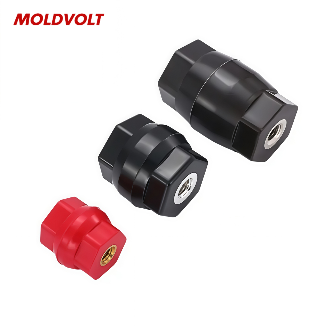
Critical Mechanical Load Demands on Insulators for Busbar Support
Static, Dynamic, and Short-Circuit Electrodynamics: Quantifying Peak Forces (Up to 250 kA)
Busbar support insulators must simultaneously manage three distinct mechanical load regimes. Static loads arise primarily from conductor weight—copper busbars contribute ~8.9 kg/m, aluminum ~2.7 kg/m—requiring support spacing typically limited to 300–500 mm to avoid excessive bending moments that risk cracking ceramic bodies or deforming polymer housings. Daily thermal cycling between 40 °C and 70 °C introduces cumulative static stress, gradually loosening mounting hardware if expansion is not accommodated.
Dynamic loads present the most severe challenge. During a short circuit, electrodynamic force between parallel busbars scales with the square of instantaneous current. At a prospective peak fault current of 250 kA and 100 mm phase spacing, the force per unit length exceeds 125 kN/m—well within the 100–200 kN/m range observed in switchgear type tests. These impulsive forces last only milliseconds but repeat at power frequency, producing a hammering effect on insulators. Highest stresses occur at phase-to-phase crossovers, sharp bends, and junctions, where lateral and torsional components compound axial loading due to conductor asymmetry and mounting geometry. Consequently, insulator designs must deliver high bending, tensile, and torsional strength—not just unidirectional load capacity.
Compliance with IEC 61439-1 and IEC 62271-1: Minimum Insulator Strength Thresholds
International standards establish enforceable mechanical integrity requirements. IEC 61439-1 for low-voltage assemblies mandates short-circuit withstand verification via calculation and type testing. While it does not prescribe a fixed safety factor, industry practice—and all major manufacturer type-test protocols—require a minimum margin of 2.0 between the insulator’s ultimate breaking load and the worst-case design force derived from the assembly’s rated peak withstand current.
IEC 62271-1 for high-voltage switchgear treats support insulators as integral to the circuit’s mechanical integrity chain. Compliance testing subjects them to simultaneous voltage and mechanical stress cycling, verifying no cracks, tracking, or functional failure. Minimum strength thresholds include static compression ratings above 50 kN for main busbar supports and bending strengths between 5–20 kN, depending on system voltage and busbar span. These values ensure structural stability and electrical isolation are maintained even during a full 250 kA fault event.
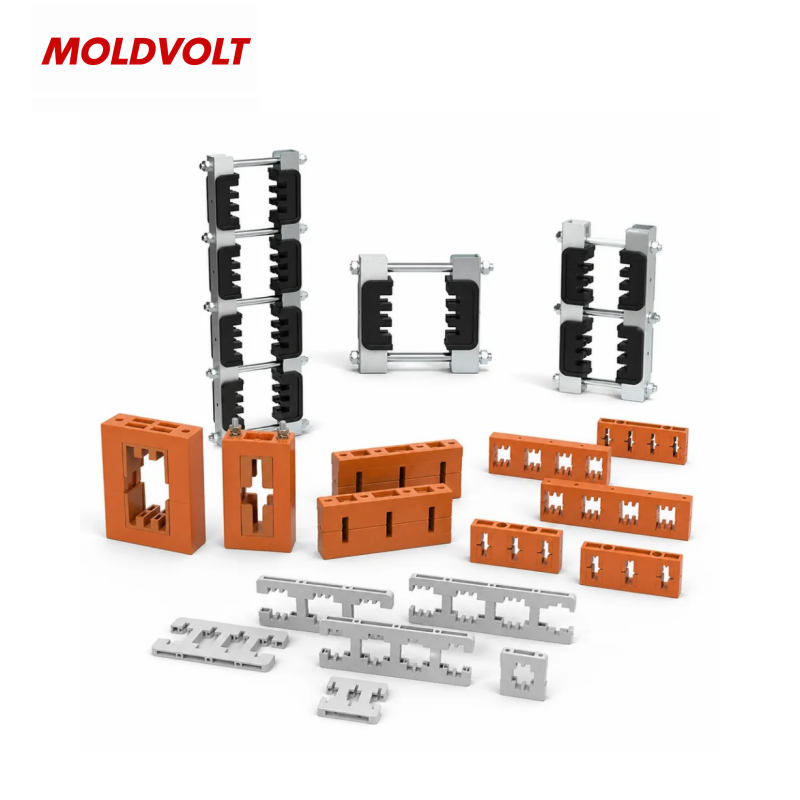
Insulator Material Selection: Ceramic vs. Composite Performance Under Real-World Stress
Compressive Yield Strength and Creep Resistance of Alumina Ceramic and Silicone-Epoxy Insulators
Material selection hinges on matching mechanical behavior to application demands. Alumina ceramic (Al₂O₃ ≥ 95%) delivers exceptional compressive strength—2,050–2,200 MPa per ASTM C773—ensuring minimal deformation under static load and preserving precise alignment critical for partial discharge control. In contrast, silicone-epoxy composites offer lower compressive yield strength (180–280 MPa) but superior toughness, enabling energy absorption during short-circuit impacts and reducing brittle fracture risk.
Creep resistance further distinguishes the two. Alumina exhibits negligible creep (<10⁻⁶ strain/year) under sustained 100 MPa loads at ambient temperatures (IEC/TR 62039, 2019). Silicone-epoxy insulators, however, display time-dependent strain: accelerated aging studies (40 °C, 90% RH) show glass-fibre-reinforced grades retain dimensional stability for over 20 years only when operating stress remains below 25% of their short-term ultimate strength. Exceeding this threshold leads to creep-induced joint loosening, increasing contact resistance and hot-spot temperatures. Field data from a leading switchgear manufacturer confirms this—installations with continuous composite support loads >30 MPa recorded a 12% rise in hot-spot temperatures over three years (internal reliability report, 2023).
| Property | Alumina Ceramic (95% Al₂O₃) | Silicone‑Epoxy Composite (GFRP) |
|---|---|---|
| Compressive yield strength (MPa) | 2,050 – 2,200 | 180 – 280 |
| Creep rate (ε/year) at 20 MPa, 40 °C | < 10⁻⁶ (negligible) | 2 × 10⁻⁴ – 5 × 10⁻⁴ |
| Modulus of elasticity (GPa) | 300 – 380 | 15 – 35 |
| Fracture toughness (MPa·m¹/²) | 3 – 5 | 8 – 15 |
This inverse performance profile dictates design strategy: ceramics excel in constant-load DC systems where clamping force retention is paramount; composites require larger cross-sections or metallic inserts to redistribute stress—impacting cabinet footprint and cost.
Thermal Cycling Stability (40–70°C) and Long-Term Mechanical Integrity of Insulator Materials
Daily thermal swings between 40 °C and 70 °C place repeated strain on insulator-conductor interfaces. Alumina’s low coefficient of thermal expansion (~8 × 10⁻⁶/K) closely matches copper, minimizing interfacial shear stress. Its vulnerability lies in thermal shock—rapid cooling can induce surface tensile stress. However, 2022 test data shows high-purity alumina remains crack-free after 500 cycles from −40 °C to +85 °C, provided heating rates stay below 5 °C/min—a condition typical of passively cooled cabinets.
Silicone-epoxy composites have a higher CTE (~30 × 10⁻⁶/K) but accommodate expansion through polymer elasticity. Per IEC 62271-1 Annex B (2020), properly post-cured parts retain >95% of initial bending strength after 3,000 cycles between −25 °C and 70 °C. Critical to long-term integrity is the resin’s glass transition temperature (Tg): formulations with Tg < 100 °C risk micro-delamination at peak operating temperatures. Six-year field data from an Asian high-temperature zone validates this—composite supports with Tg = 85 °C lost 18% of load-bearing capacity, while those with Tg = 125 °C retained full rating. Material specification—not just family choice—is decisive.
Mounting Configuration Impact on Insulator Load Distribution and Service Life
Mounting configuration governs how mechanical stress flows through the insulator and into the structure. Suboptimal setups create localized stress concentrators that accelerate fatigue—even when global loads remain within published ratings. Brittle materials like ceramic perform best under uniform axial compression; any deviation introduces tension or bending, both of which propagate micro-cracks under cyclical thermal and dynamic loading.
The mounting base design and insulator spacing directly determine whether the material’s inherent strength is fully leveraged—or undermined by preventable geometry. The table below summarizes key configurations and their impact:
| Mounting Configuration | Primary Load Distribution | Effect on Service Life |
|---|---|---|
| Vertical/Axial | Uniform compression along the insulator's axis; minimal bending moment. | Maximized lifespan due to low, predictable stress. |
| Horizontal/Cantilevered | High bending moment and shear stress concentrated at the fixed end. | Reduced lifespan due to tensile fatigue and crack propagation. |
| Underslung/Tension | Material is primarily in tension, with potential for combined stress at attachment points. | High risk, especially for ceramic; limited only to composite designs. |
| Multi-Point Clamping | Redundant load paths reduce peak stress on any single insulator. | Enhances system-level reliability and damage tolerance. |
Span length between supports exponentially affects bending moment for a given busbar mass and fault current. Shorter spans dramatically reduce peak stress—confirming that robust insulator selection must be paired with intelligent mounting system design. Only then does the published compressive strength become the true limiting factor—not a geometrically induced bending failure.
Design Validation Best Practices for Insulator-Based Busbar Fixing Systems
Validating insulator performance under realistic, combined-load conditions is the final and essential checkpoint for busbar fixing reliability. A dual approach—advanced simulation backed by standardized physical testing—ensures design margins hold across service life.
Finite Element Analysis (FEA) and Type-Test Protocols for Insulator Mechanical Certification
FEA models replicate the full spectrum of operational loads: static busbar weight, dynamic switching forces, and electrodynamic peaks up to 250 kA applied at each mounting point. By incorporating material non-linearities and contact mechanics, FEA identifies stress concentrations, predicts plastic deformation onset, and quantifies fatigue accumulation across multiple fault scenarios. This virtual prototyping informs targeted reinforcement—e.g., localized ribbing or base stiffening—before physical build.
Physical validation follows IEC 61439-1 and IEC 62271-1 type-test protocols: insulators are installed in representative busbar assemblies and subjected to repeated short-circuit tests generating design-basis forces for 0.2–0.5 seconds per event. Acceptance requires no cracking, delamination, or permanent deflection beyond allowable tolerances. Post-test visual inspection and insulation resistance measurement detect latent degradation. This integrated FEA and type-test process certifies mechanical dependability—directly underpinning switchgear safety, compliance, and service longevity.
FAQ
Why is material selection critical for busbar insulators?
Material selection determines the insulator's ability to withstand mechanical loads, static stress, dynamic forces, and thermal cycling. Alumina ceramic excels in compressive strength and creep resistance, while silicone-epoxy composites offer impact absorption and bending flexibility.
What is the role of mounting configuration in insulator performance?
Mounting configuration directs load distribution through the insulator and affects stress concentration areas. Optimal configurations like vertical axial setups maximize lifespan by maintaining uniform compression.
How does IEC compliance ensure insulator reliability?
Standards like IEC 61439-1 and IEC 62271-1 verify insulator strength through testing protocols including short-circuits and combined stress cycling, ensuring they meet safety and reliability benchmarks for operational conditions.
What are the risks of not validating insulator design?
Failure to validate design risks premature material fatigue, crack propagation, and mechanical failure during peak electrodynamic forces, compromising system safety and longevity.
Table of Contents
- Critical Mechanical Load Demands on Insulators for Busbar Support
- Insulator Material Selection: Ceramic vs. Composite Performance Under Real-World Stress
- Mounting Configuration Impact on Insulator Load Distribution and Service Life
- Design Validation Best Practices for Insulator-Based Busbar Fixing Systems
- FAQ